


We may receive a commission when you use our affiliate links. However, this does not impact our recommendations.
Many woodworking tools, like the saw, chisel and plane, go way, way back. We’ve no idea who invented them or who refined them. This jig is one of those anonymous acts of genius. How in the world did somebody come up with such a neat idea? You spin an arm around and around, and instead of tracing a circle, it outlines a perfect ellipse. Wow.
Old mechanisms like this were used by woodworkers to draw an ellipse with a pencil or stylus, which they would then cut out by hand. But if you substitute a router for the pencil, you’ll have the job done a whole lot faster!
I’ve designed the jig to work with an ultra-smooth action. It doesn’t hesitate or skip, and produces a perfectly smooth edge.
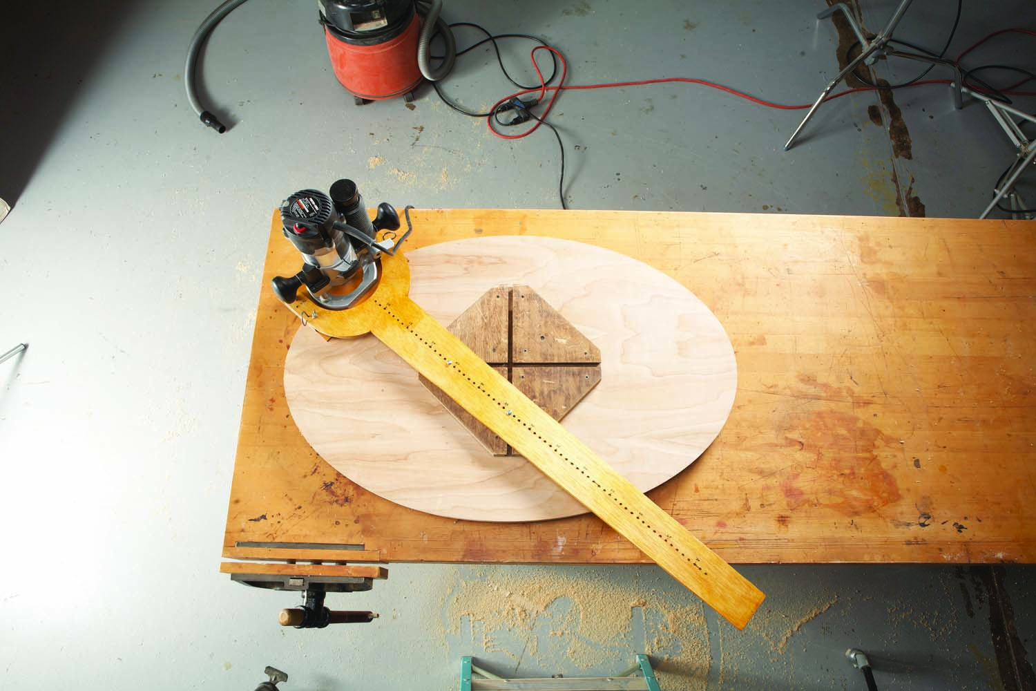
First position.
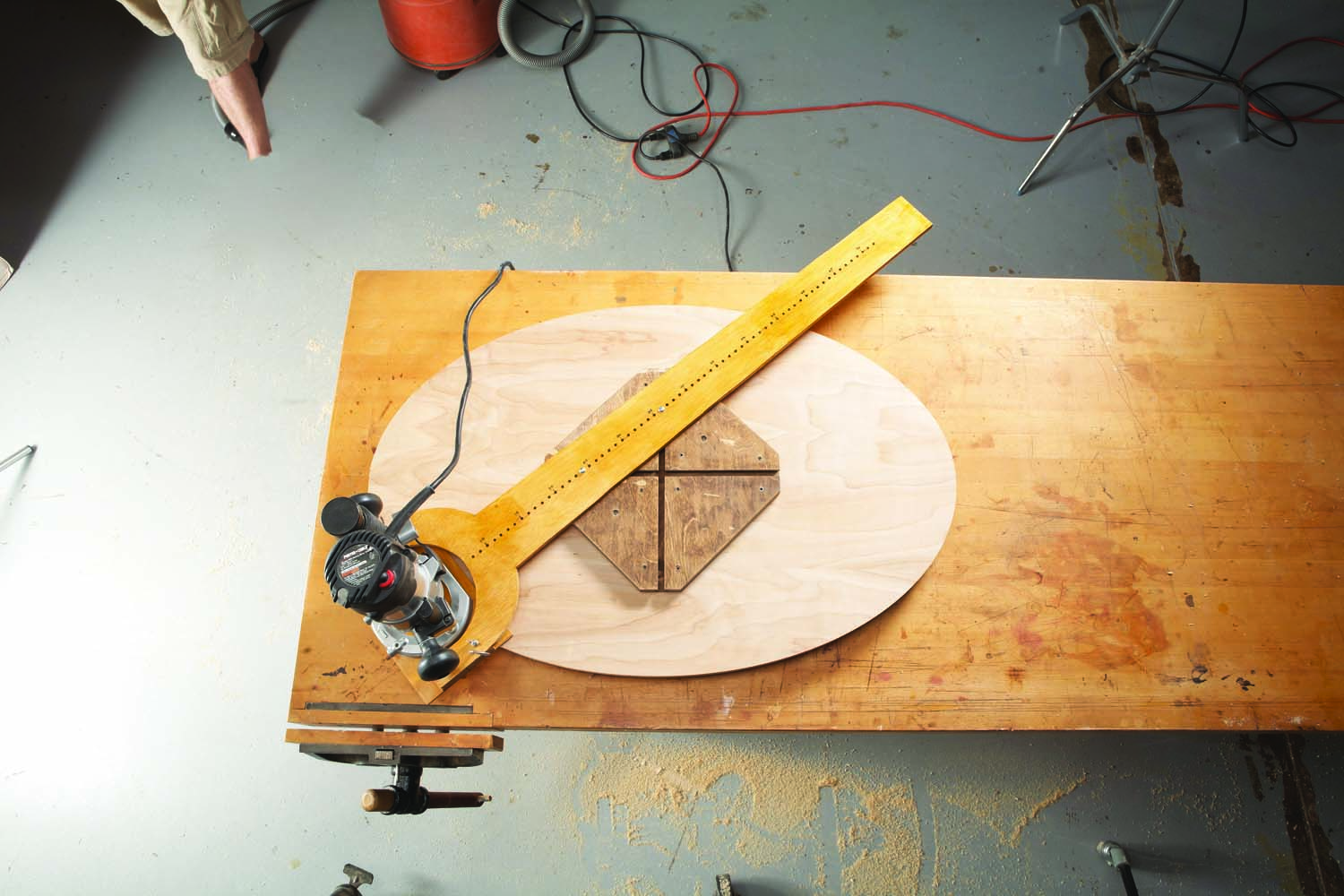
Traveling counterclockwise.
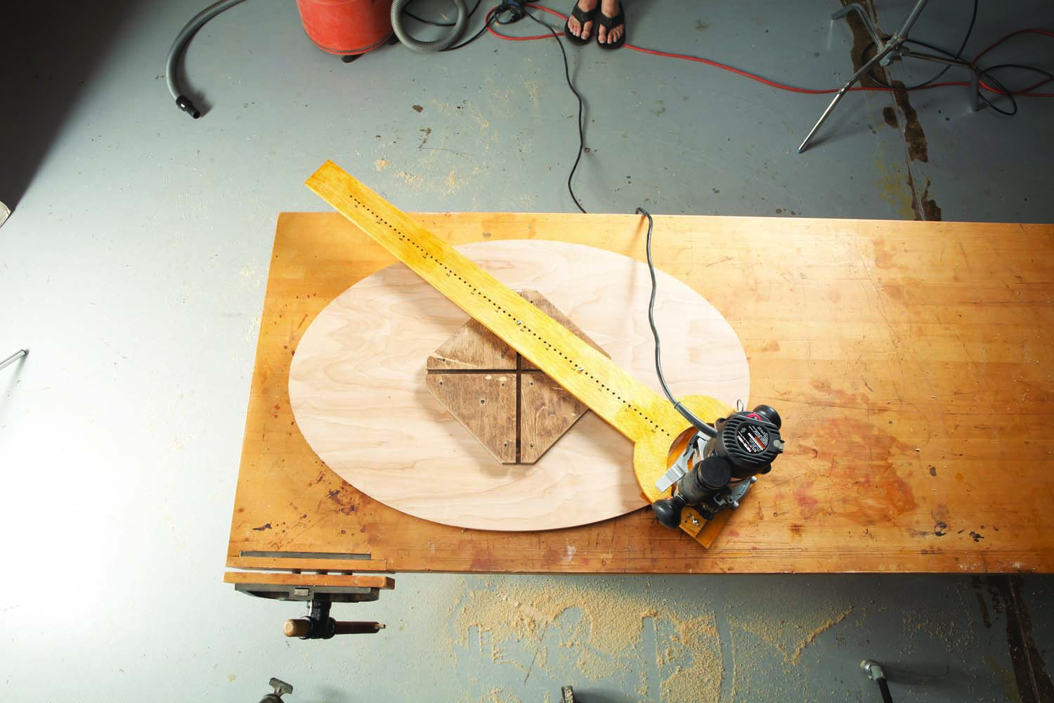
Rounding the bend.
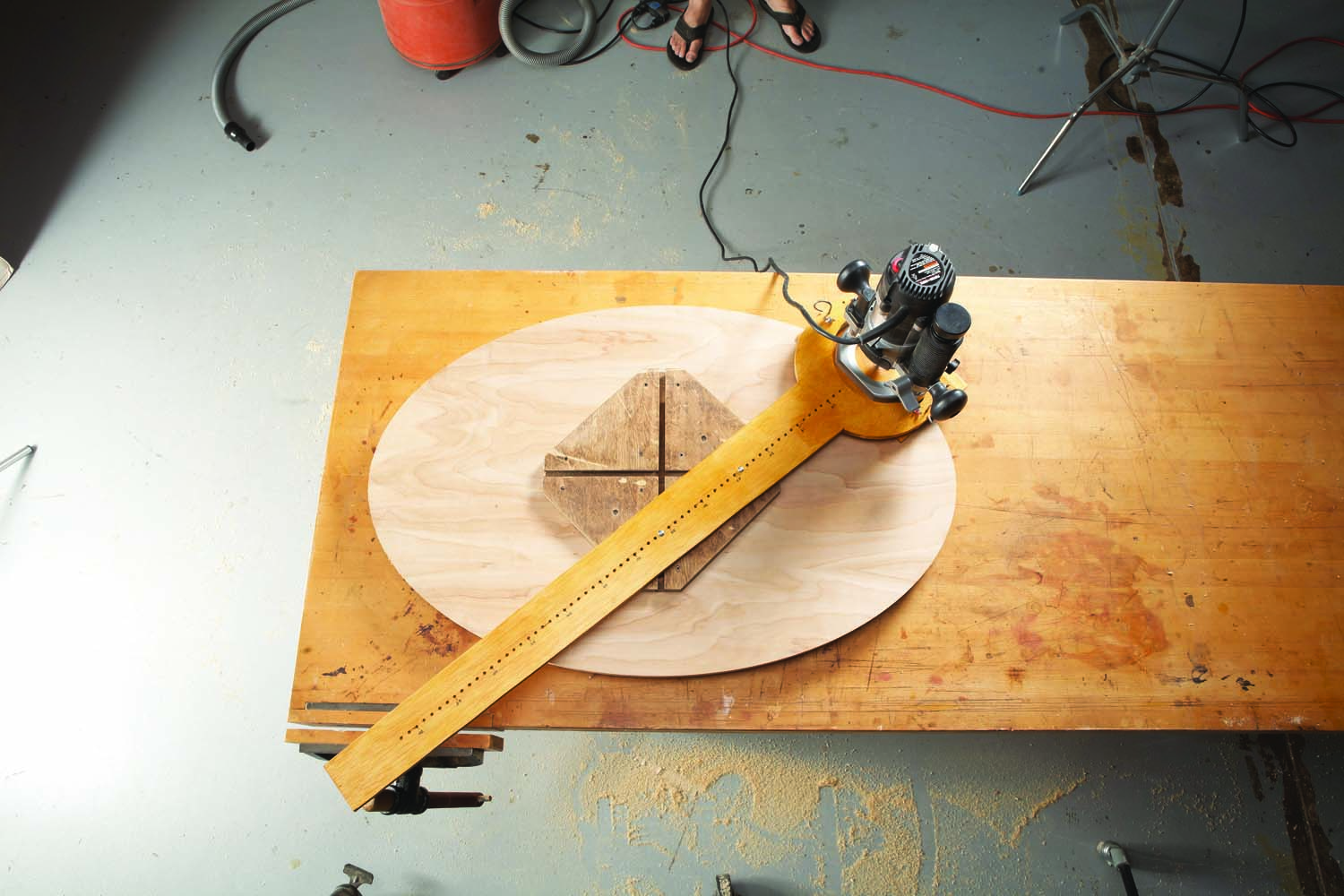
This jig works on a simple principle: Two blocks, connected to a long arm, slide back and forth in a cross pattern, while the arm rotates counterclockwise. As you rotate the arm, the blocks travel past each other. The router on the end of the arm describes in a perfect ellipse.
Part 1: Make the jig’s base
The exact dimensions of the jig’s base (A) aren’t really all that important—what counts is sticking to this design. If you want to make an ellipse that’s smaller than the range given in Fig. 08, you’ll need to make a smaller base.
For the jig to work smoothly, the sliders (B) that run in the base’s grooves must fit the grooves just so—not too tight, but not too loose. And the less friction, the better. While you could make the sliders from solid wood (maple would be best), I used UHMW plastic. This material is quite slippery and will never need lubricating.

1. Set up a dado blade to cut a groove that precisely fits a piece of 3/4″ thick UHMW plastic.
Cut the base to final size. Be sure that it’s absolutely square. Next, set up a dado set to cut a groove to fit your slider material (Photo 1). Cut two of these grooves in the base (Photo 2; Fig. 02.)
2. Cut two grooves at right angles to each other on a square piece of plywood. This is the jig’s base.
Next, make the sliders. Begin by cutting two rabbets on both ends of the piece of plastic (Photo 3; Fig. 03). I used a rabbeting bit in a router table, but a dado set would work just as well.
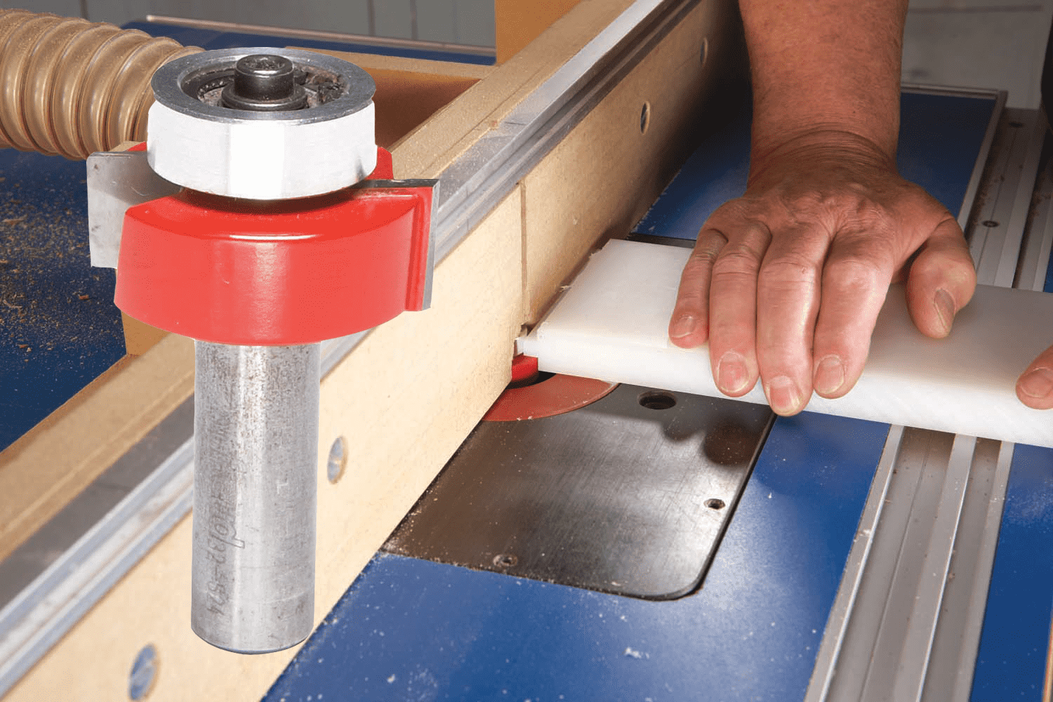
3. Rout rabbets on both sides of the plastic, forming a T-shape. Repeat this operation on the other end of the plastic.
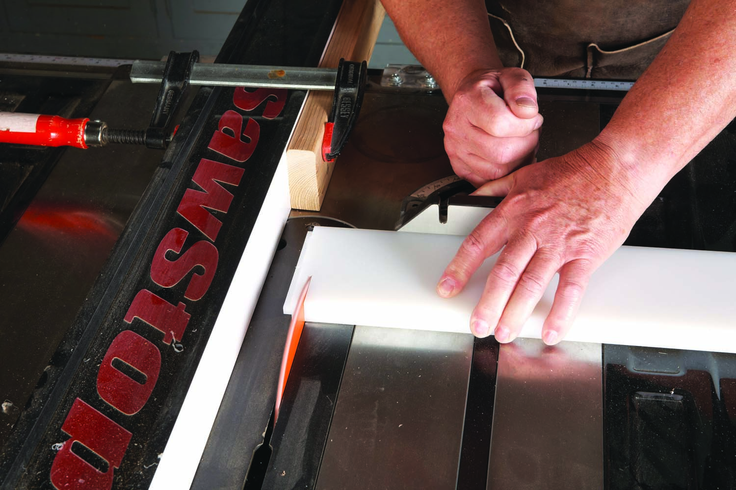
4. Cut off both ends of the plastic, creating two T-shaped “sliders.” Use a 1″ thick stop block clamped to your fence to set up this cut.
Crosscut the plastic to free the sliders (Photo 4). Note that the length of this cut will depend on the precise depth of the grooves you cut in the base. When you place each slider in a groove, the top of its upper shoulder should be about 1/64″ lower than the surface of the base. This clearance is necessary for the slider to travel freely. I clamped a 1″ thick stop block to my saw’s fence so I could use the rip scale to position the fence for this cut. If, on the first try, you make the slider too tall or too short, you won’t be able to salvage it. No problem. Just cut some new rabbets and try again. That’s why I used my router table, rather than a tablesaw, to cut the rabbets.
 Using a router table to cut rabbets, dadoes and grooves can free up your tablesaw for other work. If there’s a chance you must remake a piece, leave the router table set up as long as you can.
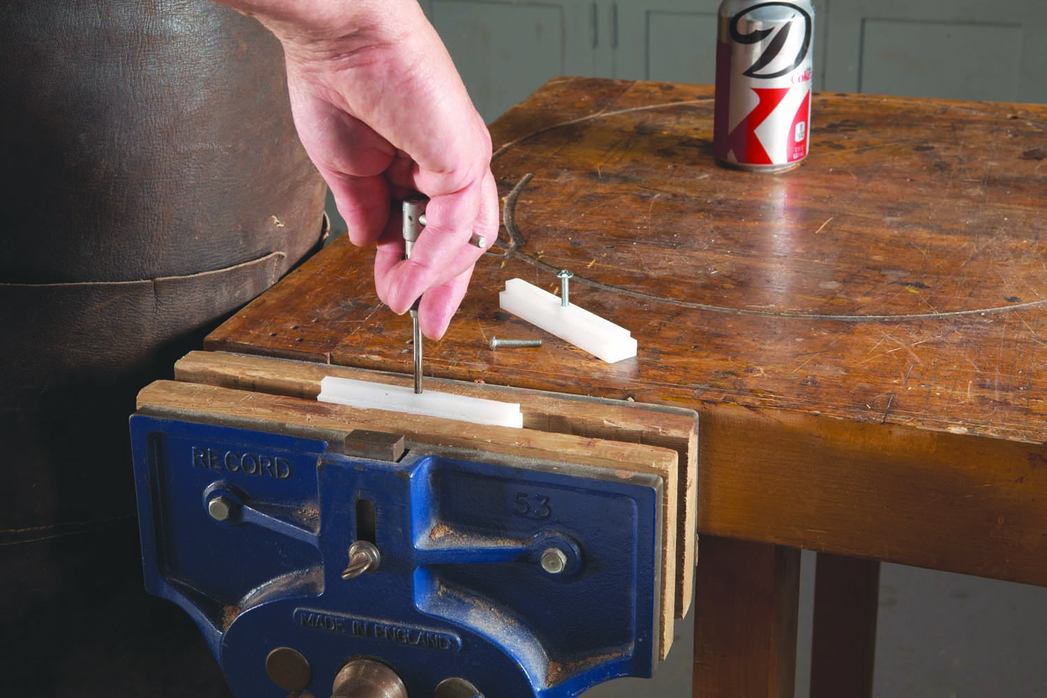
5 Tap holes in the sliders for fastening them to the jig’s arm.
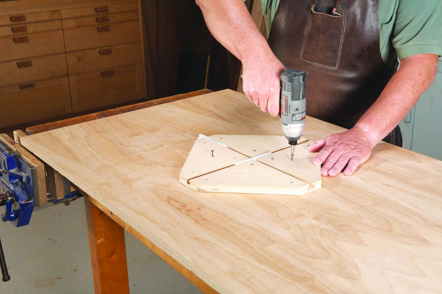
Drill holes in the middle of the sliders, then tap the holes to receive 8-32 screws (Photo 5). Place the sliders in the base. Four plates (C) prevent the sliders from lifting out of the grooves. Cut the plates to size and fasten them to the base (Photo 6).
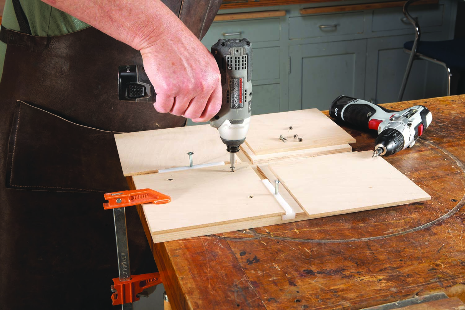
6. Put the sliders in the grooves, then trap them with four smaller pieces of plywood. Fasten these pieces to the base.
If you use ordinary plywood for the plates, which is slightly less than 1/4″ thick, the top of the sliders will sit about 1/32″ above the plates. That’s fine—this clearance is exactly what you want. When you attach the jig’s arm to the sliders, you don’t want the arm to drag on the base. It should be slightly elevated above it.
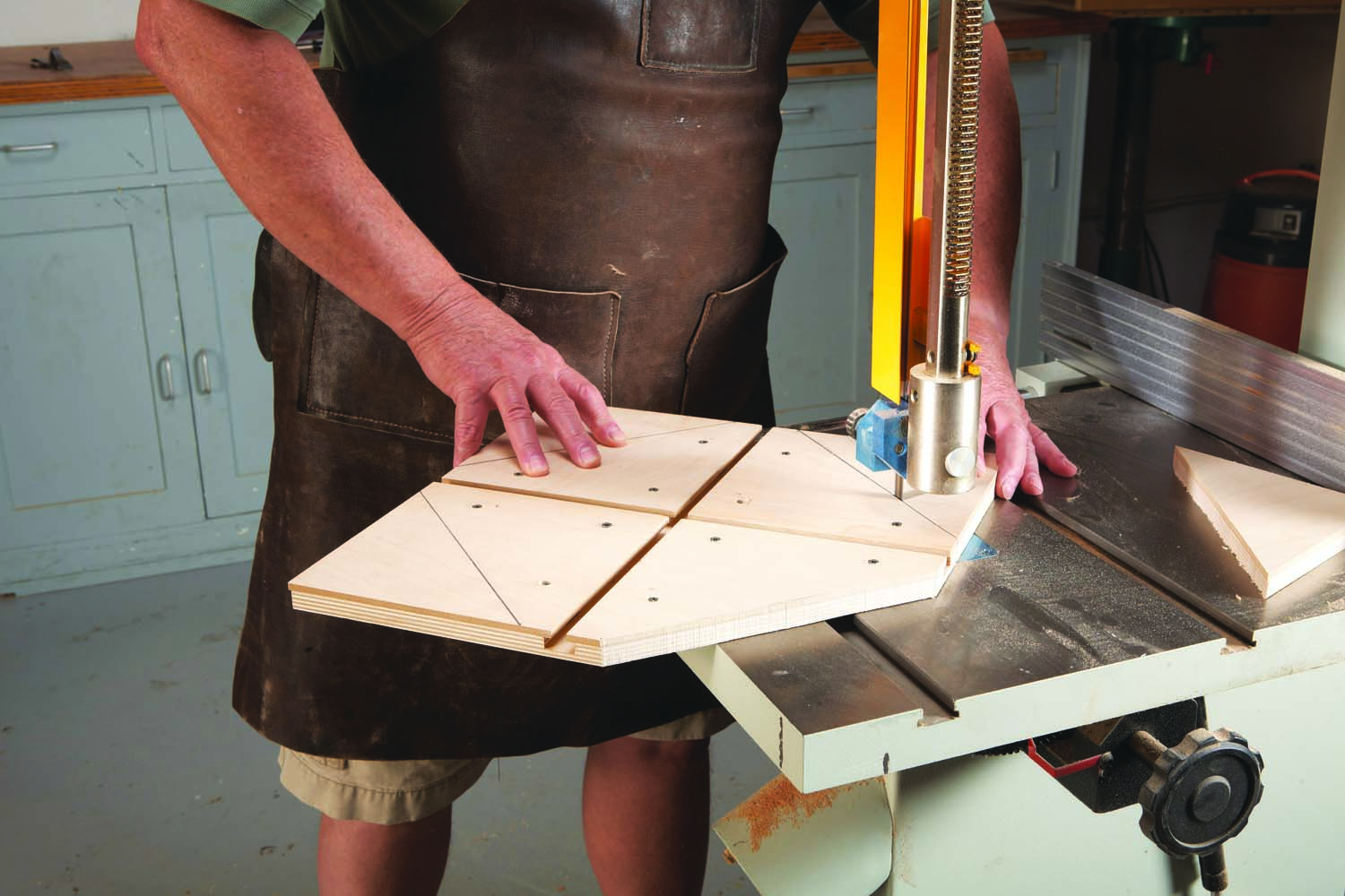
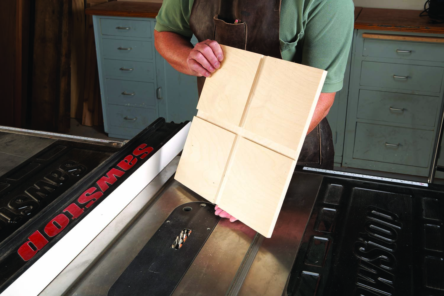
7. Cut off the corners of the jig.
To complete the base, cut off its corners (Photo 7). These cuts don’t have to be dead straight—they just reduce the base’s size for routing small ellipses.
Make the arm
The arm can be as long or short as you wish. It’s designed to place your router as close to the work surface as possible, so you don’t need an extra-long bit. You may have to modify the size of the arm’s fork to fit your router.
The arm (D) has a series of holes spaced 1/2″ apart. They allow you to quickly set up the jig to make an ellipse of any size, in increments of 1″.
Let me explain that. Ellipses are defined by two dimensions: a major diameter (the long way across) and a minor diameter (the short way across)—see Fig. 08. Think of each hole in the arm as the center of a diameter; basically, it’s the equivalent of a circle’s radius. The actual diameter will be twice the distance that the hole is from the router bit. For example, the hole labeled 10″ refers to a 10″ diameter, but it is actually only 5″ from the bit. That’s how a 1/2″ spacing between the holes yields major and minor diameters in increments of 1″. If you need to make an ellipse with fractional dimensions, say, 10-1/4″ x 15-3/8″, just drill some new holes alongside the existing holes.
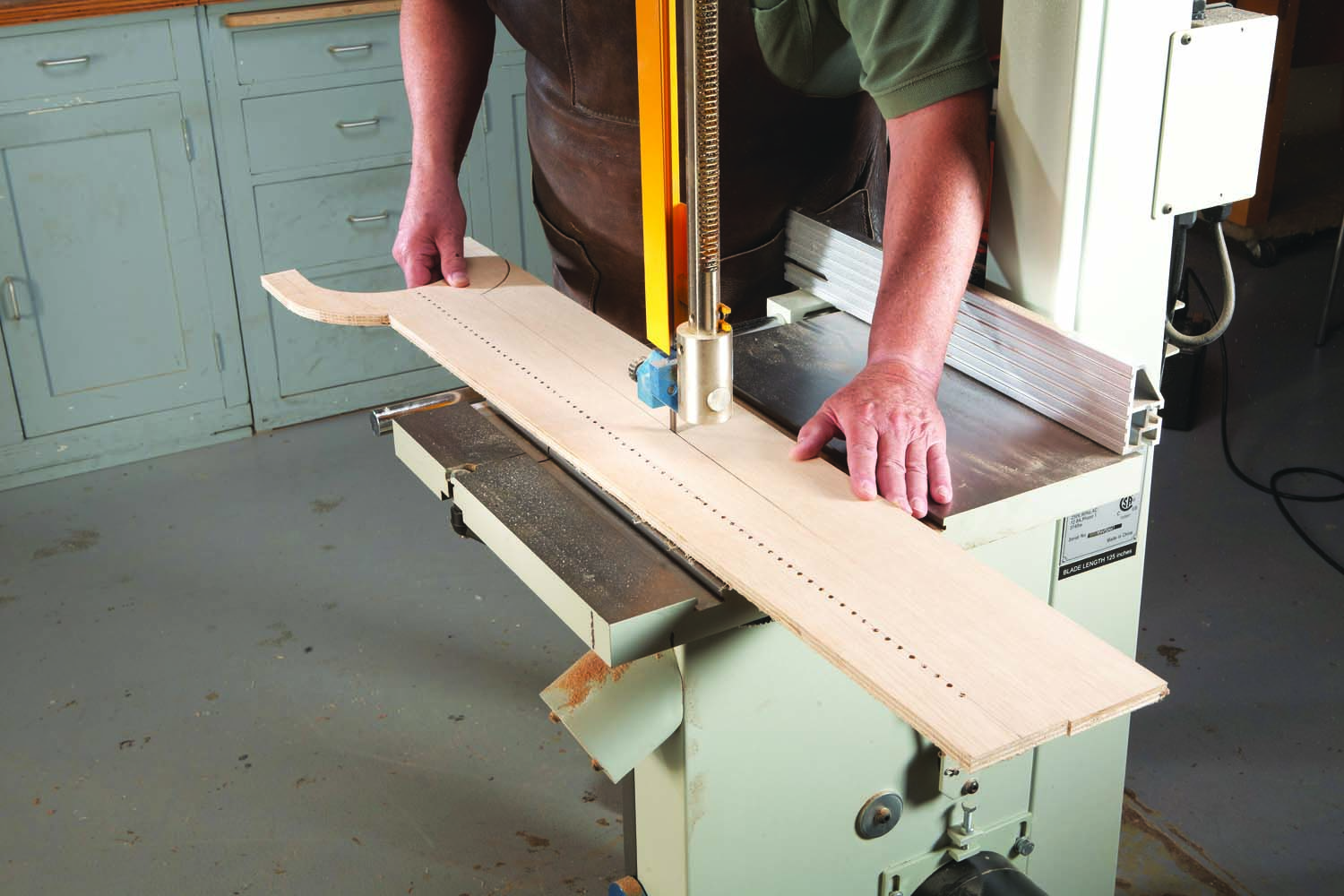
8. Make the jig’s arm. Drill holes spaced 1/2″ apart down the length of the arm, then cut out the arm’s shape.
Drill the ellipse-diameter holes and the holes for mounting the spacers (E) and platforms (F) using a drill press. Cut out the arm (Photo 8; Fig. 04). Make the spacers (Fig. 05).
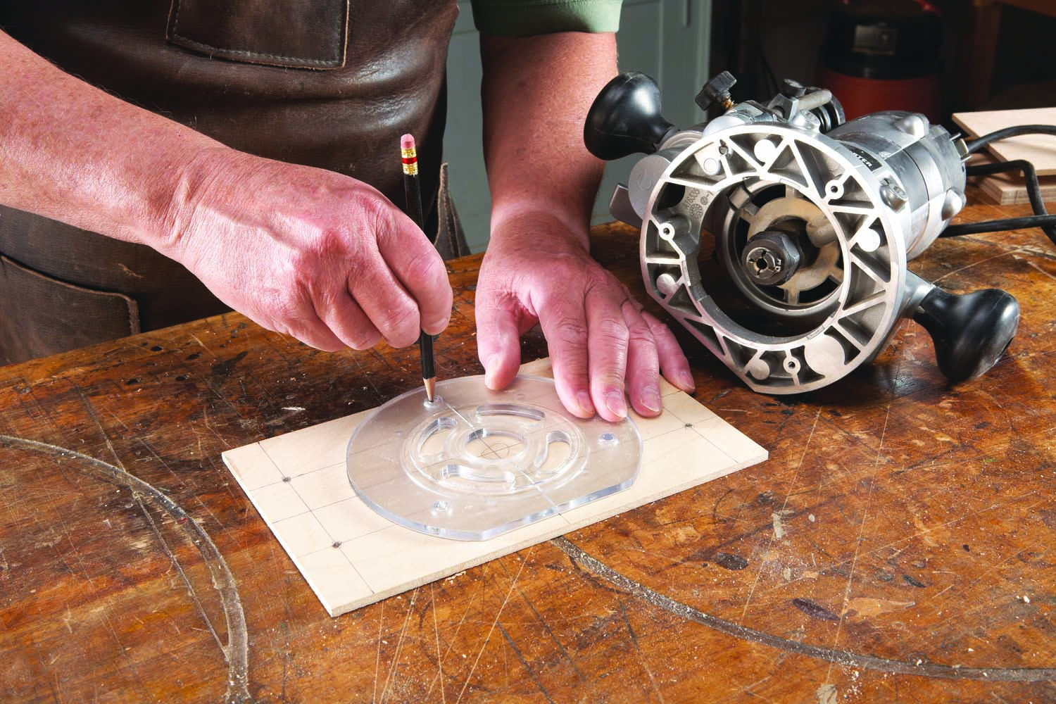
9. Make two platforms for the arm. This one will be drilled to fit a router; the other one is for use with a pencil.
Next, make the platforms (Photo 9; Figs. 06 and 07). One is for drawing the ellipse; the other is for routing it. The drawing platform has a small hole for a pencil point. When you mount the platform on the arm, this hole should be exactly 4″ from the hole marked 8″ on the arm.
The routing platform has a large hole for the bit to pass through. Note that the center of this hole is not in the same location as the center of the pencil hole. You’ll want the edge of the bit to cut right on the pencil line, so the precise location of the routing platform’s hole will depend on the diameter of the bit you’ll use. I use a 1/2″ bit.
I’ve added an optional micro-adjust feature to the arm that allows me to trim an ellipse 1/16″ smaller all around on a final pass (see Photo 15, page XX). After making a series of stepped cuts to outline the ellipse, this final cut ensures that the edge of the ellipse will be perfectly smooth. Basically, the micro-adjust allows you to move the platform 1/16″ closer to the center of the ellipse, and lock it there with a pair of indexing pins (Fig. 09). To do this, the holes in the arm that go under the wing nuts must be made oval, using a file.
Mount the routing platform on the arm before you drill the holes for the indexing pins. Note that there are two sets of these holes; they go on both sides of the platform. The distance between the holes and their exact location isn’t important; it’s their 1/16″ offset that counts. To drill the holes, loosen the wing nuts and pull the platform to its farthest position away from the center of the ellipse. Tighten the wing nuts, then drill a 1/8″ hole through the arm and down into the spacer. Move the platform in 1/16″, then drill another set of holes; label these as the “Trim” position and you’re all set.
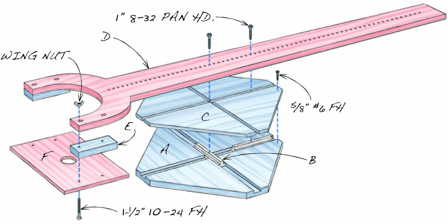
Fig. A. Exploded View
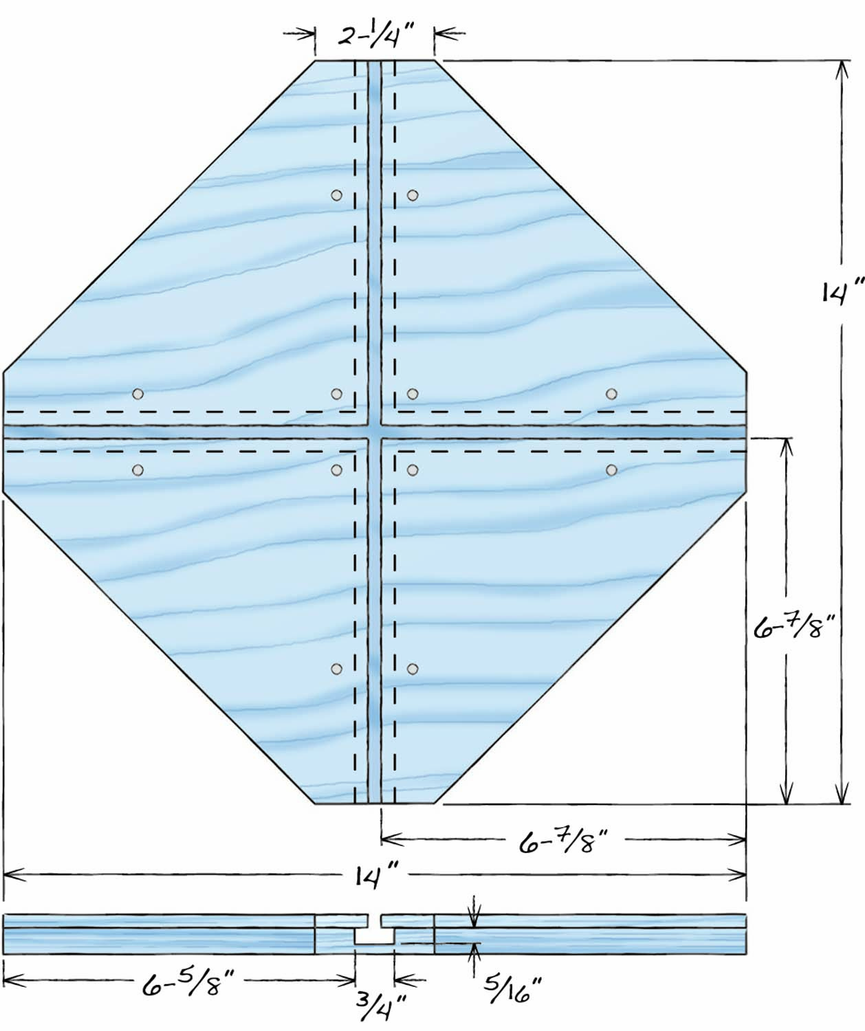
Fig. B. Base Details
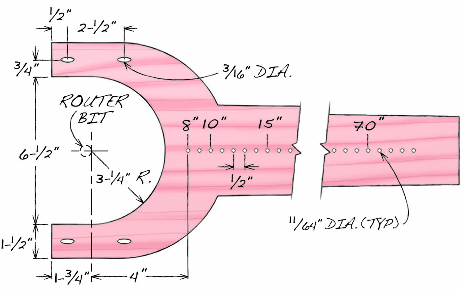
Fig. C. Arm Details
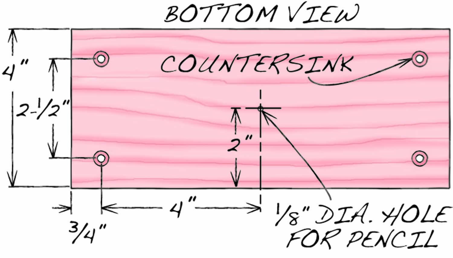
Fig. D. Drawing Platform Details
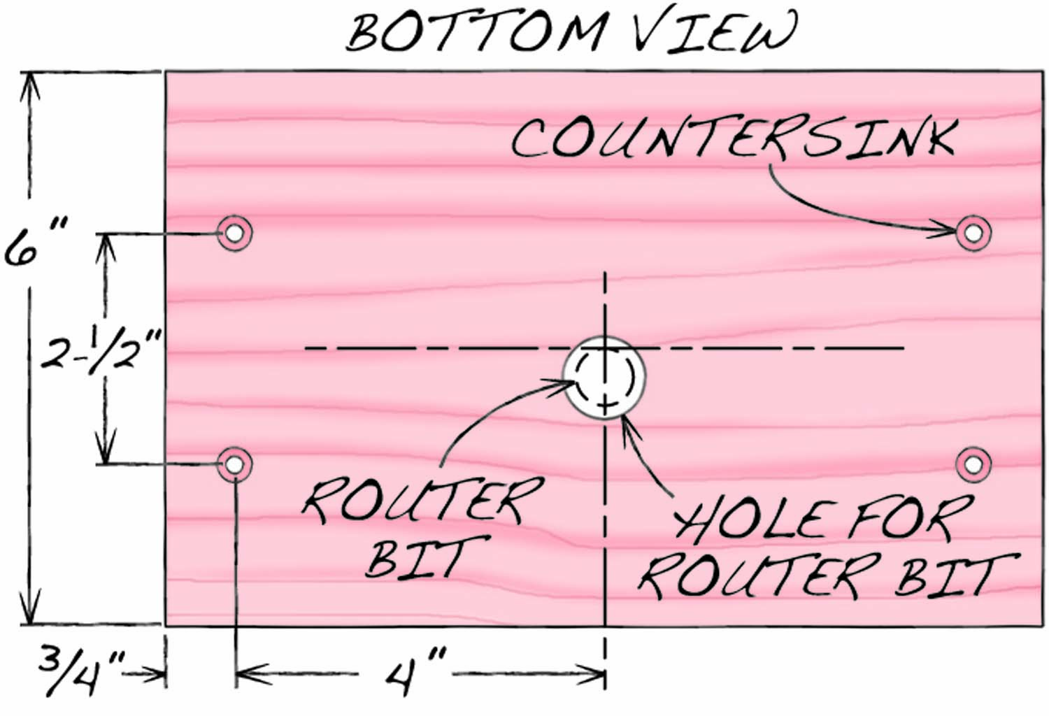
Fig. E. Router Platform Details
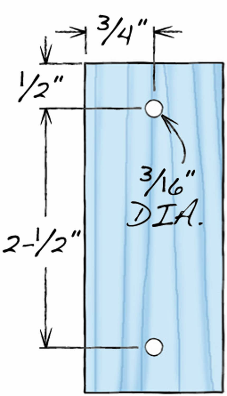
Fig. F. Spacer Details
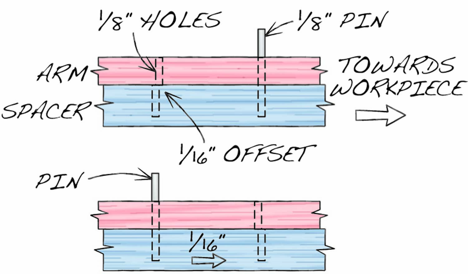
Fig. G. Micro-Adjust Details
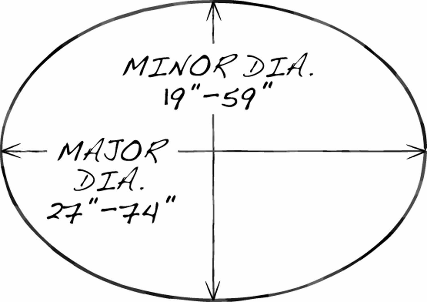
Fig. F. Range of Ellipse Sizes
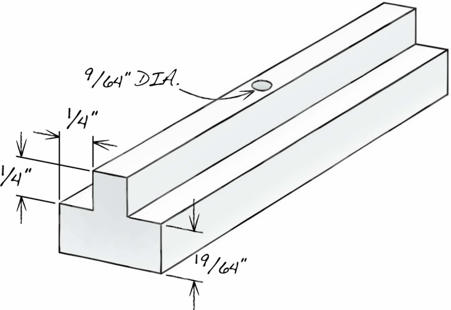
Fig. J. Slider Details
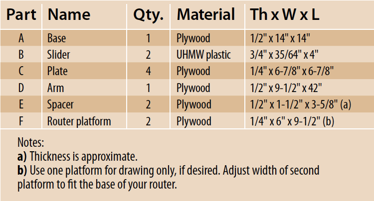
Cutting List
Rout an ellipse
The elliptical jig’s base must be fastened to your workpiece, so it can’t move. Screwing it to the underside of the workpiece is the best solution (Photo 10).
10. Fasten the jig to the workpiece. Position one slider in the middle of the cross—it will determine the ellipse’s major diameter. Position the other slider on the left hand side of the cross—it will determine the minor diameter.
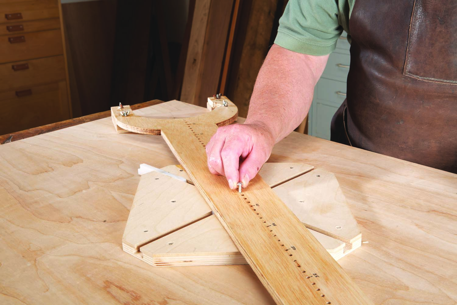
11. Mount the arm onto the major diameter slider. Using the scale on the arm, thread a screw through the appropriate hole and into the slider.
Place the sliders in the position shown in Photo 10, then mount the drawing platform onto the arm. Attach the arm to each slider (Photos 11 and 12). Lining up the second hole with its slider can be a bit awkward; using an awl first usually does the trick.
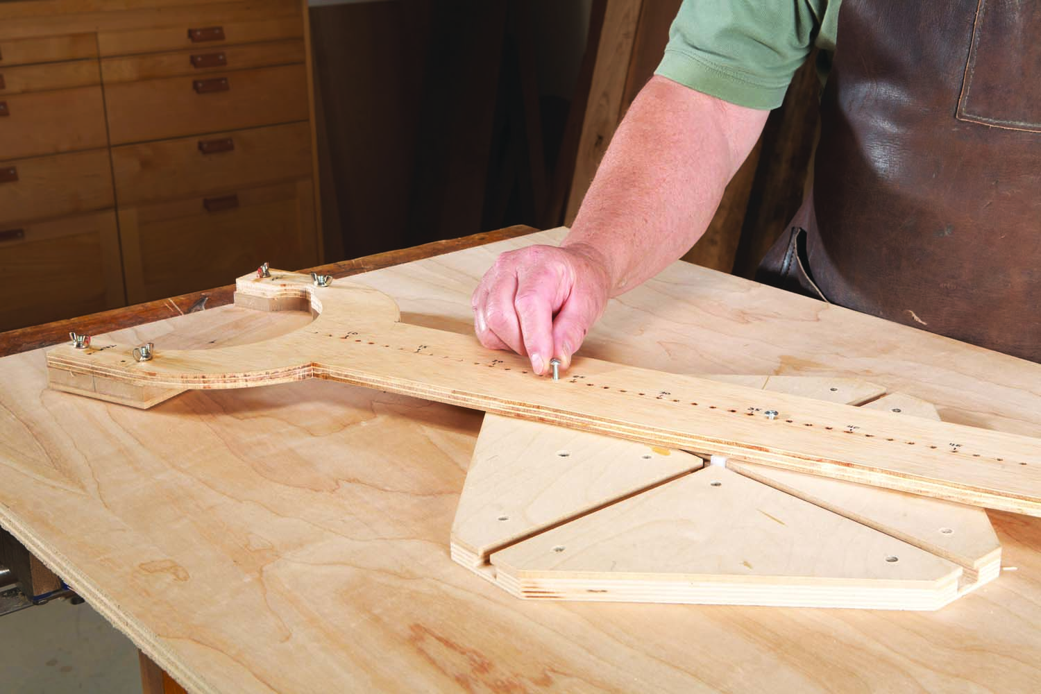
12. Mount the arm onto the minor diameter slider. Move the slider back and forth until it is in line with the correct hole on the scale, then insert a second screw.
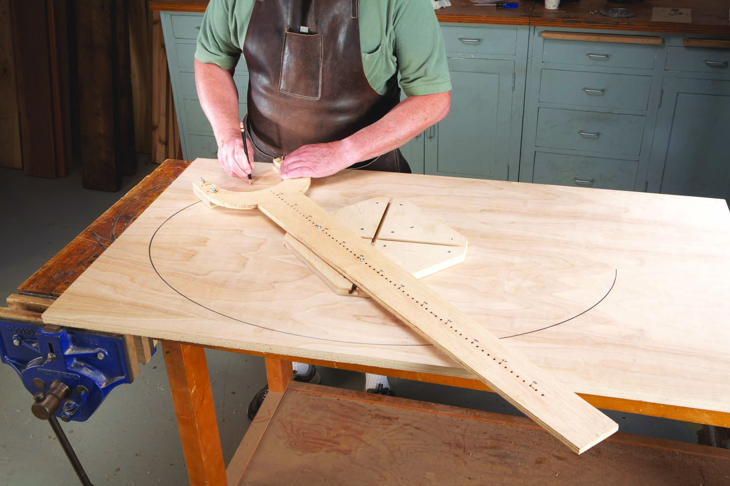
13. Use the pencil platform to draw the ellipse. Use a jigsaw or bandsaw to remove the waste, staying about 1/8″ away from the line.
Draw the ellipse (Photo 13), then remove the arm from the base and saw near the line to remove most of the waste. Place some non-slip blocks on your bench and put the workpiece on the blocks.
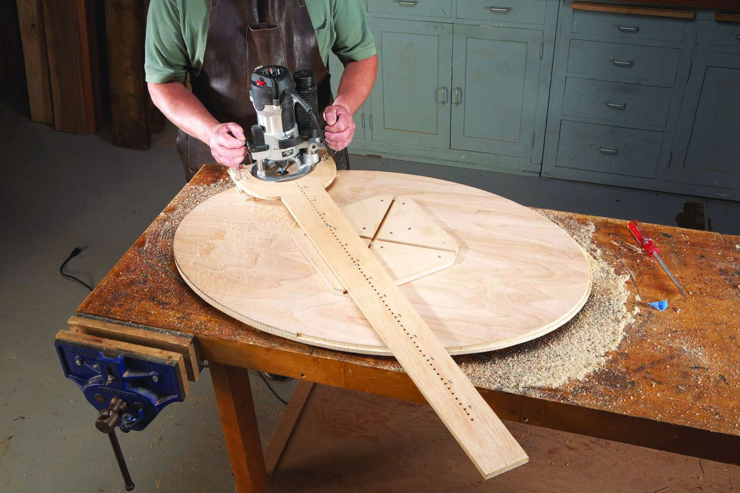
14. Mount a plunge router and its platform onto the arm. Rout around the ellipse a number of times, cutting a little bit deeper on each pass.
Remove the drawing platform and substitute the routing platform, with the router attached. Re-fasten the arm to the base and you’re ready to rout (Photo 14). Remember to go in a counterclockwise direction, as you would when routing the profile of any piece.
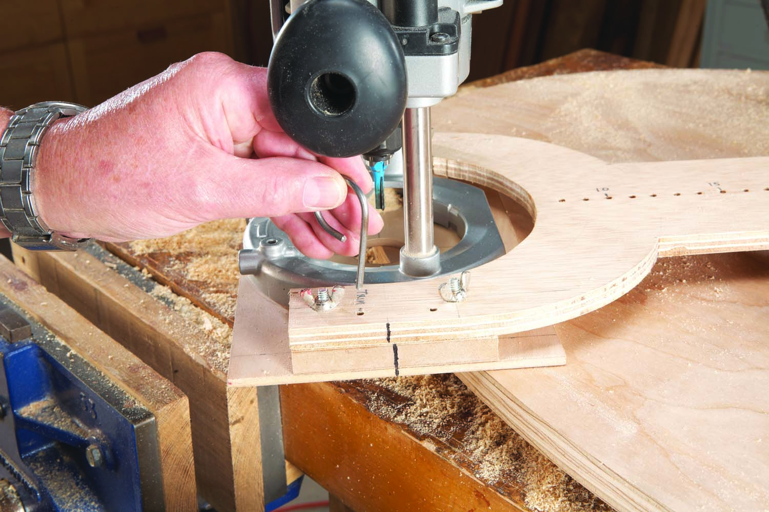
15. Adjust the platform to move the bit about 1/16″ closer to the center of the ellipse. Lock the platform’s position with a pin. Make one final, full depth pass.
If making stepped cuts resulted in a slightly uneven edge, cut a new edge using the micro-adjust feature (Photo 15).
Here are some supplies and tools we find essential in our everyday work around the shop. We may receive a commission from sales referred by our links; however, we have carefully selected these products for their usefulness and quality.


My mistake: I thought it was an older article.
I know this is an old article, but thanks for reposting it for us “newer woodworkers”. Nice build for a jig!
I have looked at many designs for an elliptical jig and most of them have a few things in common and a few differences. I really like your design in using plastic for the sliders and for having the arm float above the base. Both of these seem like they would make the movement much smoother than most. I also noticed the possible dimensions would include making an ellipse of 24 x 48. However, in most jigs this would require some sort of removable extension to the base as the router wouldn’t be able to pass it to make that part of the cut. Have you come across this problem and, if so, found a reasonable solution? Thanks for your input! Victor